The SatPC32 Scope for the IC-9700
A. General
As of
December, 2019, SatPC32 has a 'Scope' that evaluates the
corresponding data output from the ICOM IC-9700 and displays it as a
spectrum line and/or waterfall. Unfortunately, with other radios, the
scope can not be used due to a lack of data.
This function assumes that CAT control is performed through the IC-9700's CI-V connector so that the radio's USB port can be used solely to receive the scope data. Using only one port conflicts between the incoming CAT data and the consistent stream of scope data. So you need an ICOM CT-17 or compatible CAT interface for the CAT control. The most convenient solution is an ICOM CAT cable (CT-17 cable) that connects the CI-V port of the IC-9700 directly to a USB port on the PC. The price is about 25$. Use only cables with FTDI chipset. Scope data requires only a single A/B USB cable that connects the device's USB port to another USB port on the PC.
The scope function is deactivated by default. The CAT control of the IC-9700 can be done as with the previous program versions using only one cable, even a simple A/B USB cable.
B. Activation of scope function
To
activate the Scope function, please proceed as follows:
Connect
the CI-V port and the USB port of the IC-9700 to the PC as described
above.
1. Turn on the radio and start SatPC32. You may receive error messages. Click them away, the program will be displayed normally.
2. Open the menu 'Setup' > 'Scope Setup'. In the SatPC32 Scope Setup menu, enter the same radio-generated COMPort number you use for CAT control via the USB port. The baud rate must be 115200. If you have not changed the default address of the IC-9700, enter either hexadecimal $A2 or decimal 162. Leave the other presets in the menu unchanged. Save the changes.
If you are currently using the USB port on the radio for CAT control, you can leave the settings on the IC-9700 (Menu > Set > Connectors > CI-V > page 2/3) unchanged. However, make sure that the baud rate is 115200.
3. Open the menu 'Setup' > 'Radio Setup'. Enter the COMPort number generated by your Icom CAT cable, baud rate 19200, Icom address $A2. Leave the other settings in this menu unchanged. (Satellite mode activated). Save the changes.
Settings on the radio: Make sure that the settings on the radio (Menu > Set > Connectors > CI-V > page 1/3) are the same. My settings on this menu page are: Baud rate 19200, CI-V address A2h, Transceive: Off, USB LAN transc. Address 00h.
Result: If you change the CAT control between CI-V port and USB port, or vice versa, you do not need to make any changes to the radio.
4. Open the SatPC32 'Options' menu. Activate the new item 'Activate Scope Functions'. Save the change and restart SatPC32.
5. Open the SatPC32 menu 'Accy' and click on 'Spectrum'. The scope window should open and be active immediately.
C. Scope Setup
The settings for
the scope functions are made in the menu 'ScopeSetup', which can be
called up both from the main program (menu 'Setup' > 'ScopeSetup')
and from the scope window with 'Setup'.
1. Regarding the choice of the COM port, the baud rate and the ICOM address see above B.2.
2. The IC-9700 allows the determination of 3 fixed edge frequency bands (segments) per band. Since the 23cm band is used in satellite mode only as an uplink band, only the 2m and 70cm band are eligible for such segments.
In the 2m band, the satellite range extends from 145,800 to 146,000 MHz. This segment should therefore be determined as 1st. The other two are arbitrary. However, they must not be greater than 1 MHz.
In the 70cm band, the satellite range is between 435.000 and 438.000 MHz. It is therefore possible, e.g. to set 3 ranges of 1 MHz each.
The procedure is described in the menu itself: To configure the segments of the 2m band chooses a satellite with downlink in the 2m band, e.g. AO-07, for the 70cm band one with downlink in the 70cm band, e.g. FO-29. Next, select the number of the segment (1 - 3). Then determine the start and end frequency of the segment. To do this, enter the values in KHz into the text fields. Allowed are only full 100 KHz. So you only need to adjust the 1-MHz and 100-KHz digits for the preset values.
Then click on 'OK'. This sends the values to the IC-9700.
3. For the waterfall you can determine different color combinations of 3 colors for the background and the signal.
4. The signal strengths are very different, depending on the frequency range and other circumstances such as the use of a preamplifier. There are therefore various options for customization. One of them are the 'Waveform Data Range' options. The 'Data Range' ranges from 0 to 160 (p. 24 of the CI-V manual). With the setting '50%' the values are halved, with the setting '25%' divided by 4. The Y values of the spectrum line are reduced accordingly. Further adjustments are made in the 'Scope' window.
5. In addition, the 'Sweep' speed can be changed in the setup window, however, the effect is small.
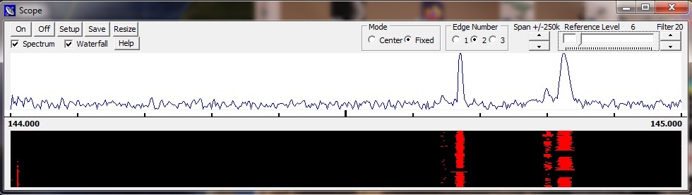
D. The following settings can be made
in the scope window itself:
1. Display of the spectrum line and/or
the waterfall.
2. 'Center' or 'Fixed' mode
The
'Center' mode is particularly suitable for satellite operation.
When
a satellite is selected, the program sets the radio to the initial
frequency specified in the 'Doppler.SQF' file, usually the band
center frequency. The passband of the satellite can then be observed
by selecting a suitable 'span' value (25 - 100 KHz).
In 'Fixed'
mode, one of the three segments defined for the band in question can
be called up.
3. The radio can be tuned to an
existing signal or any other frequency with the VFO dial, the 5
up/down controls (to the right of the frequency window), by the
direction keys of the keyboard or by mouse click on the spectrum or
waterfall.
All tuning options require that the CAT control is
acivated (C = C+). Tuning via the VFO dial works, but the frequency
changes will be canceled with the next automatic Doppler correction.
Tuning is disabled with FM satellites, it can be enabled, however, by
switching control V to V+.
4. With the keyboard of a desktop PC
the frequncy steps are:
Page up/down
+/- 5 KHz
Pos1/Ende
+/- 1 KHz
Insert/Del
+/- 20 Hz
Right/Left
+/- 500 Hz
Up/Down
+/- 100 Hz
The Right/Left and the Up/Down key
pairs are very convenient for tuning around the passband and fine
tuning as well. The keys are available on each PC keyboard, even on
those of Laptops.
Fine tuning can additionally be done with the
mouse wheel. The step is 50 Hz, with CW signals 20 Hz.
5. The 'Reference Level' slider is the most important setting option for the signal strength. It allows the deflection in the spectrum line to be set to a suitable value. With the waterfall function, it also influences the change between the signal and background color.
6. The latter is also done by the 'Filter' control. This determines the Y value at which the program chooses the signal color. In my experience, setting 10 leads to suitable results.
By combining the setting options, the level of the spectrum line and the change between signal and background color in the waterfall area can be set to usable values.